ESP Weather Station
21.04.2020 13:07 by chris
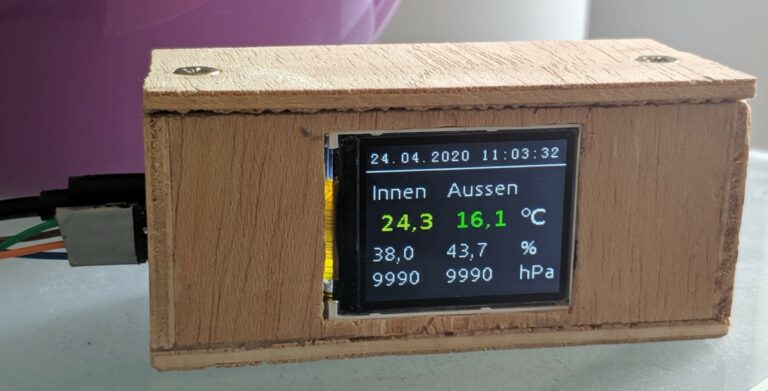
The ESP weather station is a school project. It uses a ESP32 SoC (System-On-a-Chip), two Bosch BME280 sensors and a ST7735S 1,77” TFT display to show the current indoor and outdoor temperature, humidity and pressure.
It also delivers these values over WiFi using a minimalist HTTP server.
Hardware
17:54 by chris
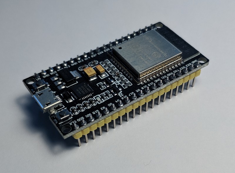
- The ESP32 is a general purpose microcontroller from espressif, which is cheap (my board costs ~10€) and has a low power consumption.
- It is Arduino compatible, so it can be programmed using the Arduino platform tools, which a lot of people are used to. On the other hand, there is the ESP-IDF, which is a device specific framework from espressif under MIT-license. With this framework all device specific quirks can be used, but therefore it is not compatible with other microcontrollers.
- It comes with integrated WiFi und Bluetooth capability, which made it’s predeseccor, the ESP8266, quite popular.
- Supports UART, I²C, SPI, I2S, PWM, SDIO, ADC, DAC
- Links: datasheet, pinout
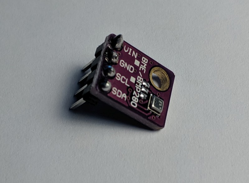
- The Bosch GY-BME280 is a digital barometric pressure sensor. It has a compact design and runs with 1.2V … 3.6V so it’s a good fit for the ESP (3.3 V).
- It operates between 300 … 1100 hPa and -40 … 85 °C.
- It can be connected using a I²C or a SPI bus.
- Links: product website, datasheet
1,77” ST7735S TFT color display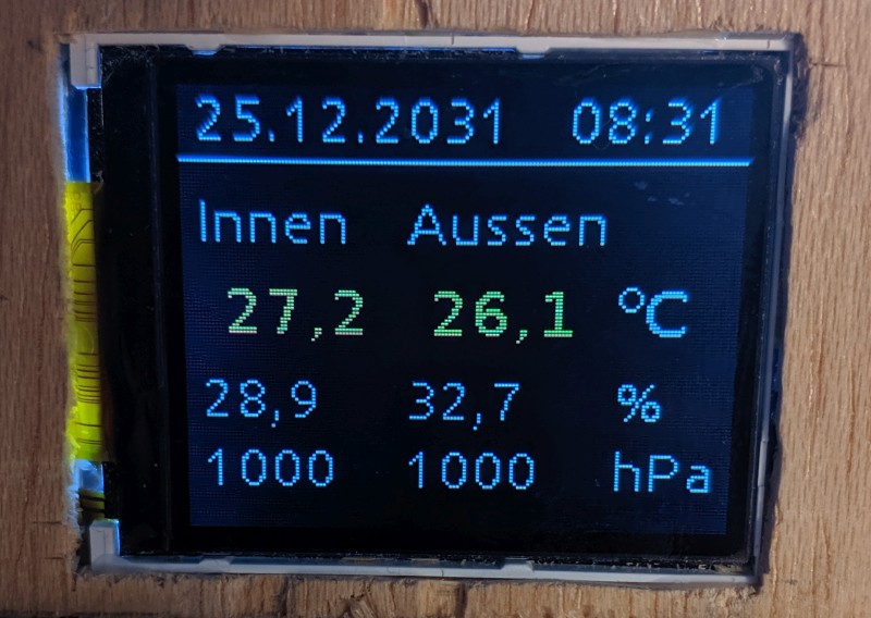
- 1,77 inch (~4,5 cm) color display with 128×160 pixels
- Very cheap (~8€)
- SPI bus
- The display is supported by several libraries like ucgib and ESP32_TFT_library.
- I first tried to supply a HAL for ucglib, since it is implemented on the Arduino framework and not the ESP-IDF, but then experienced very bad performance. Therefore I tried the ESP32_TFT_library (ESP-IDF version 4 fork by jeremyjh). This library uses a custom made SPI driver for the ESP32 and is a lot faster than my custom made HAL.
- Links: product website, datasheet
5V 0.5A USB power adapter
Wiring
27.04.2020 03:45 by chris
This is a schematic of the wiring of the weather station:
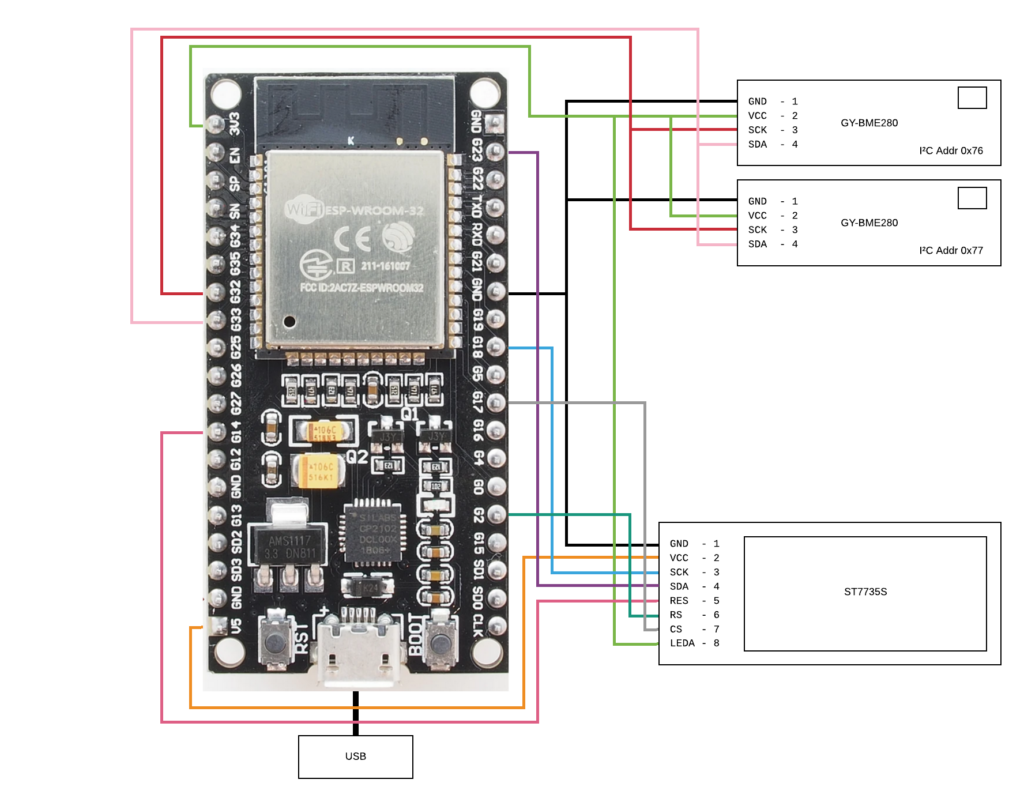
The two barometric sensors are connected by I²C to the ESP. Mine both had the I²C address of 0x77 in their original state, so a second I²C port would have been necessary. I tried a drastic measure following a forum post of Koepel on the offical Arduino forums, which involved cutting a connection on the board. The first try killed the sensor, but in the second try the operation was successful and the sensor switched to address 0x76.
The TFT display receives it’s data over a SPI bus port from the ESP32. There are also a reset pin and a 3.3 V pin for the backlight connected.
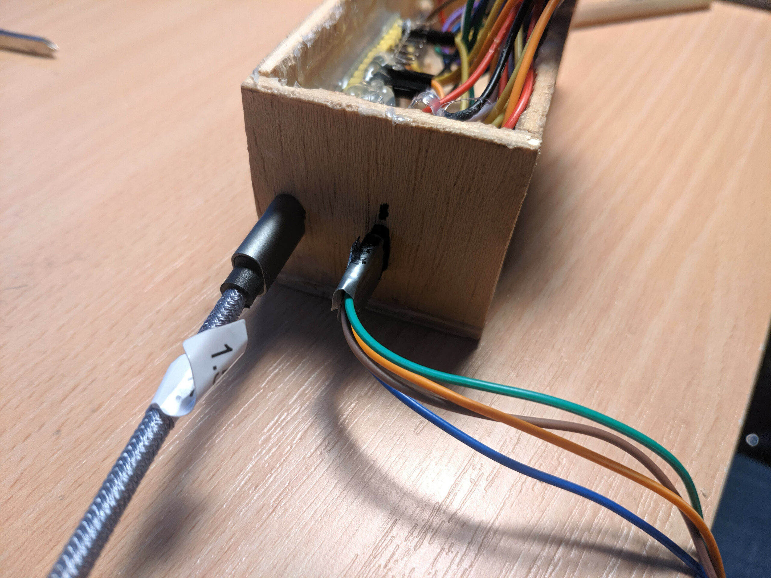
This setup is implemented using a perfboard and a lot of cables:
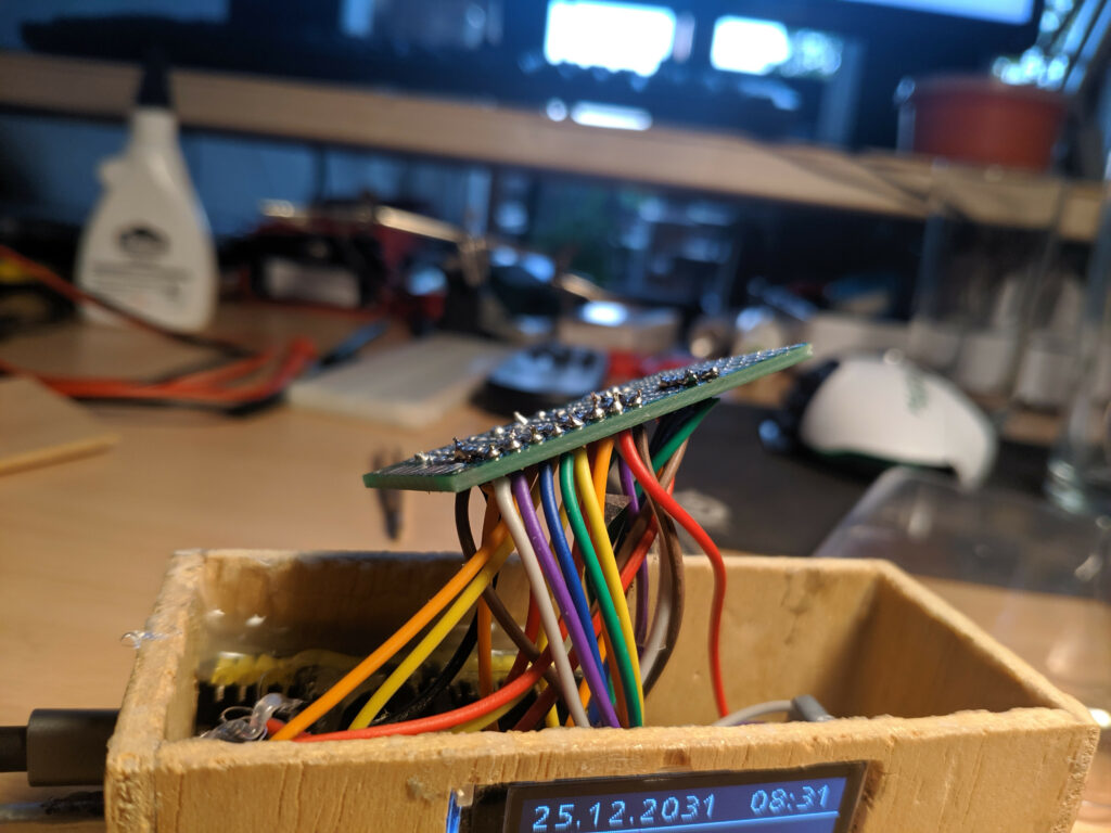
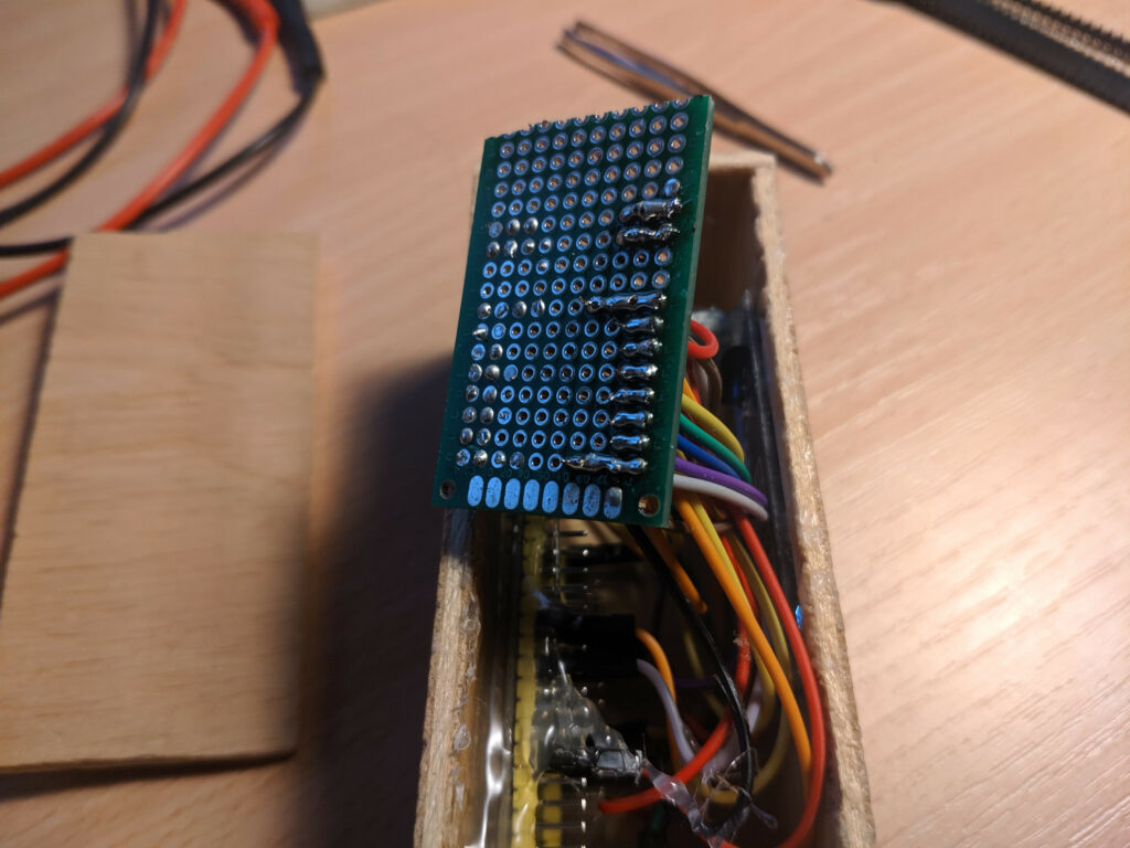
The left side is a failed try and not in use.
The external sensor and the usb power adapter are connect through sockets on the side cover:
Component architecture
20:05 by chris
In the following, you can find a UML component diagram of the software architecture:
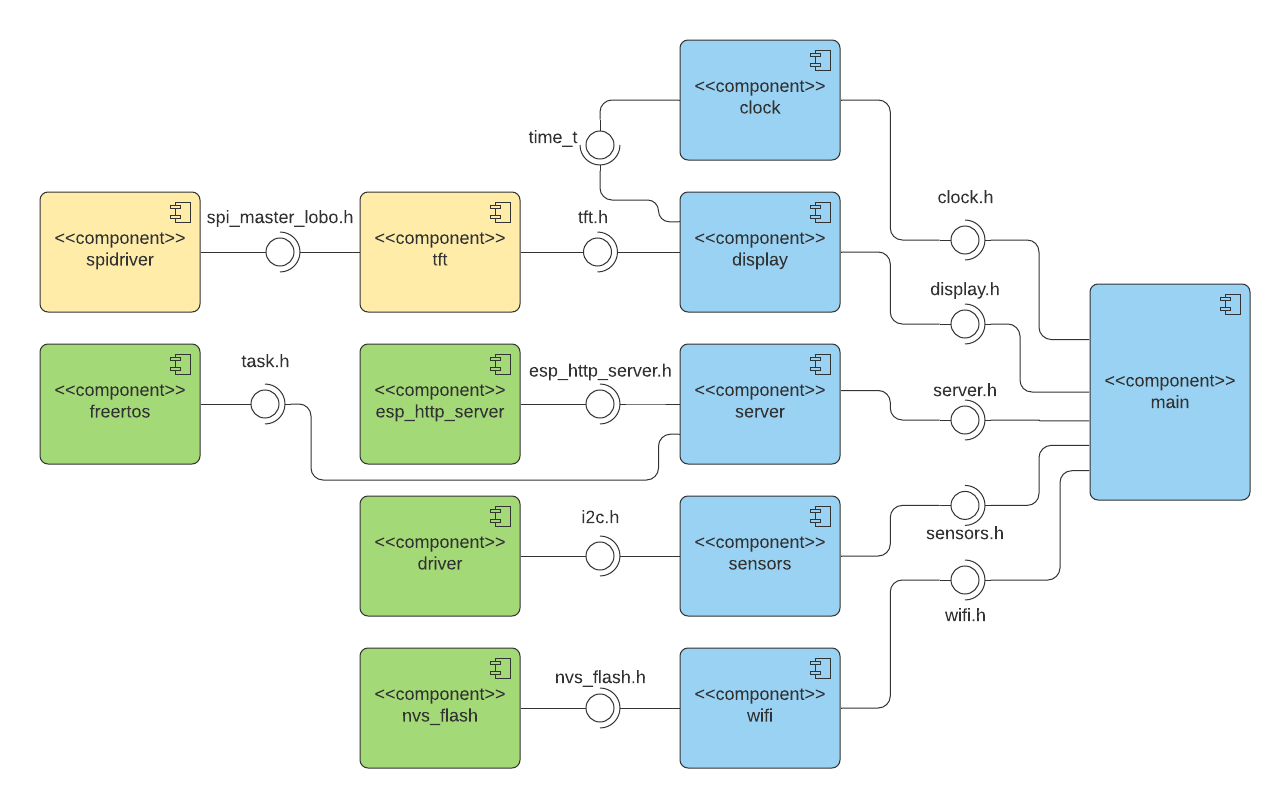
The blue colored components are developed by myself for this project. The yellows are integrated from the ESP32_TFT_library to control the display and the greens originate from the ESP-IDF.
Sensors Component
23:52 by chris
The sensors component controls the barometric sensors. It has the functions in it’s export interface:
- Init sensors at the start:
void init_sensors() - Start a measurement on the first sensor and write results to pointer parameters:
@param temp: pointer to the memory region for the resulting temp
@param press: pointer to the memory region for the resulting pressure
@param humid: pointer to the memory region for the resulting humidity
void read_sensor(int32_t* temp, uint32_t* press, uint32_t* humid); - Equivalent for the second sensor:
read_sensor2(...)
The component uses the provided Bosch library. It implements all device specific commands and measurement correction, but needs an interface for communication being implemented on the platform it runs on. The functions of the interface are:
I²C Delay
void user_delay_ms(uint32_t period)
{
    /*
     * Return control or wait,
     * for a period amount of milliseconds
     */
}
Implementation:
void i2c_delay(uint32_t period) {
    vTaskDelay(period / portTICK_PERIOD_MS);
}
I²C Read
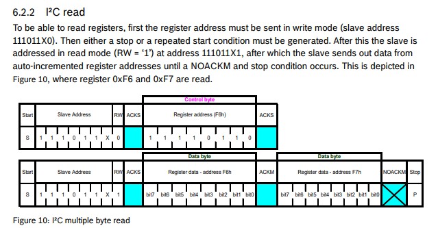
int8_t user_i2c_read(uint8_t dev_id, uint8_t reg_addr, uint8_t *reg_data, uint16_t len)
{
    int8_t rslt = 0; /* Return 0 for Success, non-zero for failure */
    /*
     * The parameter dev_id can be used as a variable to store the I2C address of the device
     * Data on the bus should be like
     * |------------+---------------------|
     * | I2C action | Data                |
     * |------------+---------------------|
     * | Start      | -                   |
     * | Write      | (reg_addr)          |
     * | Stop       | -                   |
     * | Start      | -                   |
     * | Read       | (reg_data[0])       |
     * | Read       | (....)              |
     * | Read       | (reg_data[len - 1]) |
     * | Stop       | -                   |
     * |------------+---------------------|
     */
    return rslt;
}
Implementation:
int8_t i2c_read(uint8_t dev_id, uint8_t reg_addr, uint8_t *data, uint16_t len) {
	i2c_cmd_handle_t cmd = i2c_cmd_link_create();
	i2c_master_start(cmd);
	i2c_master_write_byte(cmd, dev_id << 1 | I2C_MASTER_WRITE, 1);
	i2c_master_write_byte(cmd, reg_addr, 1);
	i2c_master_start(cmd);
	i2c_master_write_byte(cmd, dev_id << 1 | I2C_MASTER_READ, 1);
	if (len > 1) {
		i2c_master_read(cmd, data, len - 1, I2C_MASTER_ACK);
	}
	i2c_master_read_byte(cmd, data + len - 1, I2C_MASTER_NACK);
	i2c_master_stop(cmd);
	i2c_master_cmd_begin(I2C_NUM_0, cmd, 500 / portTICK_RATE_MS);
	i2c_cmd_link_delete(cmd);
	return 0;
}
I²C Write
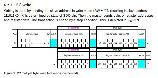
int8_t user_i2c_write(uint8_t dev_id, uint8_t reg_addr, uint8_t *reg_data, uint16_t len)
{
    int8_t rslt = 0; /* Return 0 for Success, non-zero for failure */
    /*
     * The parameter dev_id can be used as a variable to store the I2C address of the device
     * Data on the bus should be like
     * |------------+---------------------|
     * | I2C action | Data                |
     * |------------+---------------------|
     * | Start      | -                   |
     * | Write      | (reg_addr)          |
     * | Write      | (reg_data[0])       |
     * | Write      | (....)              |
     * | Write      | (reg_data[len - 1]) |
     * | Stop       | -                   |
     * |------------+---------------------|
     */
    return rslt;
}
Implementation:
int8_t i2c_write(uint8_t dev_id, uint8_t reg_addr, uint8_t *data, uint16_t len) {
	i2c_cmd_handle_t cmd = i2c_cmd_link_create();
	i2c_master_start(cmd);
	i2c_master_write_byte(cmd, (dev_id << 1) | I2C_MASTER_WRITE, 1);
	i2c_master_write_byte(cmd, reg_addr, 1);
	i2c_master_write(cmd, data, len, 1);
	i2c_master_stop(cmd);
	i2c_master_cmd_begin(I2C_NUM_0, cmd, 500 / portTICK_RATE_MS);
	i2c_cmd_link_delete(cmd);
	return 0;
}
After implementing these interface functions, you can use the library functionality to read from the sensors.
The I²C driver from the ESP-IDF needs to be initialized first:
void i2c_setup()
{
	printf("Setting up I2C driver on port 1... ");
	i2c_config_t config;
	config.mode = I2C_MODE_MASTER;
	config.sda_io_num = 33;
	config.sda_pullup_en = GPIO_PULLUP_ENABLE;
	config.scl_io_num = 32;
	config.scl_pullup_en = GPIO_PULLUP_ENABLE;
	config.master.clk_speed = 100000;
	i2c_param_config(I2C_NUM_0, &config);
	printf("Set driver parameters... ");
	esp_err_t err = i2c_driver_install(I2C_NUM_0, I2C_MODE_MASTER, 0, 0, 0);
	if (err == ESP_OK)
		printf("Driver installed!\n");
	else if (err == ESP_ERR_INVALID_ARG)
		printf("Driver install failed, invalid arguments!\n");
	else
		printf("Driver install failed!\n");
}
Above is just ESP-IDF functions, the Bosch libs are not used until know.
Then you need to fill a config struct for a sensor:
dev = malloc(sizeof(struct bme280_dev));
dev->dev_id = 0x76;
dev->intf = BME280_I2C_INTF;
dev->read = i2c_read;
dev->write = i2c_write;
dev->delay_ms = i2c_delay;
bme280_init(dev);
And finally there can a measurement be started:
void read_sensor(int32_t* temp, uint32_t* pressure, uint32_t* humidity) {
	uint8_t settings_sel;
	uint32_t req_delay;
	struct bme280_data comp_data;
	dev->settings.osr_h = BME280_OVERSAMPLING_16X;
	dev->settings.osr_p = BME280_OVERSAMPLING_16X;
	dev->settings.osr_t = BME280_OVERSAMPLING_16X;
	dev->settings.filter = BME280_FILTER_COEFF_16;

	settings_sel = BME280_OSR_PRESS_SEL | BME280_OSR_TEMP_SEL | BME280_OSR_HUM_SEL | BME280_FILTER_SEL;
	bme280_set_sensor_settings(settings_sel, dev);

	req_delay = 12*bme280_cal_meas_delay(&(dev->settings));

	bme280_set_sensor_mode(BME280_FORCED_MODE, dev);
	dev->delay_ms(req_delay / portTICK_PERIOD_MS);
	bme280_get_sensor_data(BME280_ALL, &comp_data, dev);
	*temp = comp_data.temperature;
	*pressure = comp_data.pressure;
	*humidity = comp_data.humidity;
}
Here a measurement with maximum oversampling is started in forced mode (the sensor immediatly takes the measurement and goes back to sleep afterwards). The compensation data is calibration data in the sensor and is used to correct the readings. After the measurement is taken, the results are stored in the memory regions of the corresponding pointers.
Links
28.04.2020 00:32 by chris
| Source Code Repo | https://git.skalarprodukt.de/chris/Weather_ESP |
| ESP-IDF Docs | https://docs.espressif.com/projects/esp-idf/en/release-v4.0/api-reference/index.html |
| I²C Description (german) | https://www.rahner-edu.de/grundlagen/signale-richtig-verstehen/i2c-besser-verstehen-1/ |
| Bosch BME driver repo | https://github.com/BoschSensortec/BME280_driver |