ESP Weather Station
21.04.2020 13:07 by chris
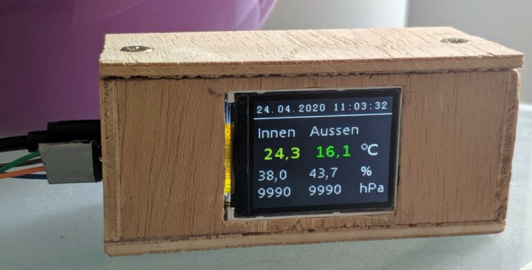
The ESP weather station is a school project. It uses a ESP32 SoC (System-On-a-Chip), two Bosch BME280 sensors and a ST7735S 1,77” TFT display to show the current indoor and outdoor temperature, humidity and pressure.
It also delivers these values over WiFi using a minimalist HTTP server.
Hardware
17:54 by chris
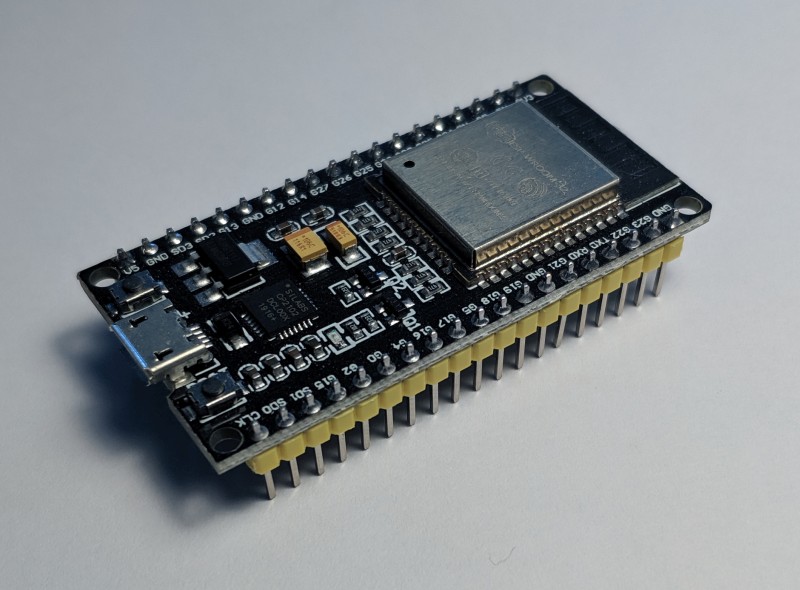
- The ESP32 is a general purpose microcontroller from espressif, which is cheap (my board costs ~10€) and has a low power consumption.
- It is Arduino compatible, so it can be programmed using the Arduino platform tools, which a lot of people are used to. On the other hand, there is the ESP-IDF, which is a device specific framework from espressif under MIT-license. With this framework all device specific quirks can be used, but therefore it is not compatible with other microcontrollers.
- It comes with integrated WiFi und Bluetooth capability, which made it’s predeseccor, the ESP8266, quite popular.
- Supports UART, I²C, SPI, I2S, PWM, SDIO, ADC, DAC
- Links: datasheet, pinout
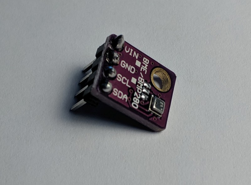
- The Bosch GY-BME280 is a digital barometric pressure sensor. It has a compact design and runs with 1.2V … 3.6V so it’s a good fit for the ESP (3.3 V).
- It operates between 300 … 1100 hPa and -40 … 85 °C.
- It can be connected using a I²C or a SPI bus.
- Links: product website, datasheet
1,77” ST7735S TFT color display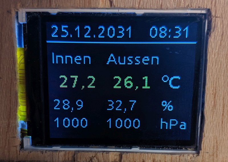
- 1,77 inch (~4,5 cm) color display with 128×160 pixels
- Very cheap (~8€)
- SPI bus
- The display is supported by several libraries like ucgib and ESP32_TFT_library.
- I first tried to supply a HAL for ucglib, since it is implemented on the Arduino framework and not the ESP-IDF, but then experienced very bad performance. Therefore I tried the ESP32_TFT_library (ESP-IDF version 4 fork by jeremyjh). This library uses a custom made SPI driver for the ESP32 and is a lot faster than my custom made HAL.
- Links: product website, datasheet
5V 0.5A USB power adapter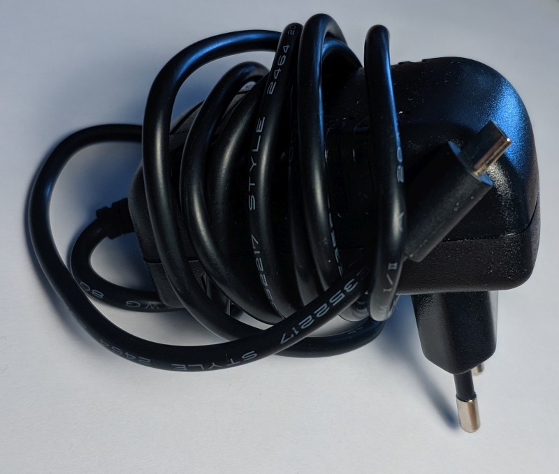
Wiring
27.04.2020 03:45 by chris
This is a schematic of the wiring of the weather station:
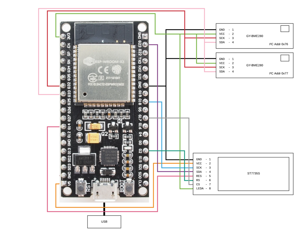
The two barometric sensors are connected by I²C to the ESP. Mine both had the I²C address of 0x77 in their original state, so a second I²C port would have been necessary. I tried a drastic measure following a forum post of Koepel on the offical Arduino forums, which involved cutting a connection on the board. The first try killed the sensor, but in the second try the operation was successful and the sensor switched to address 0x76.
The TFT display receives it’s data over a SPI bus port from the ESP32. There are also a reset pin and a 3.3 V pin for the backlight connected.
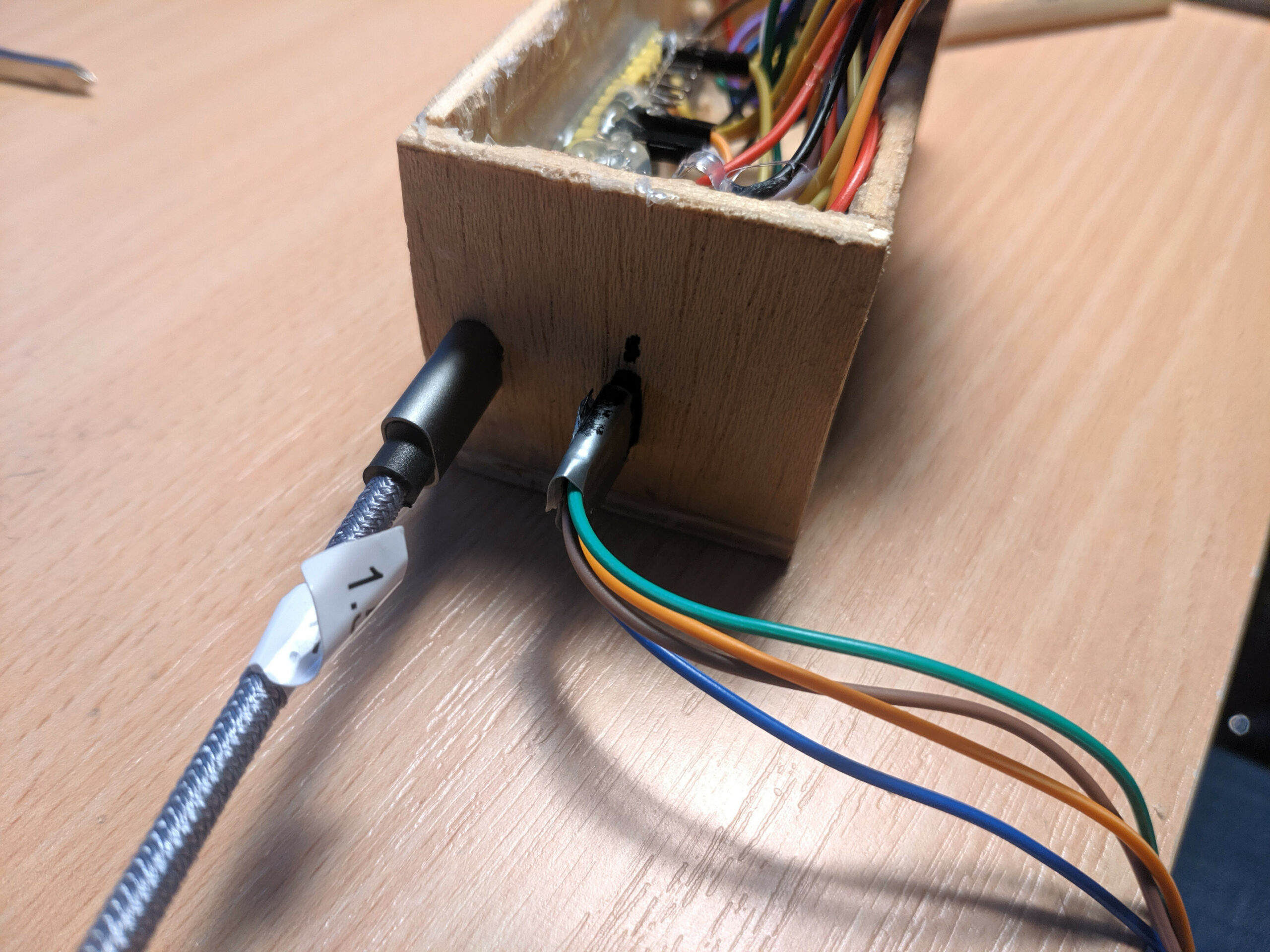
This setup is implemented using a perfboard and a lot of cables:
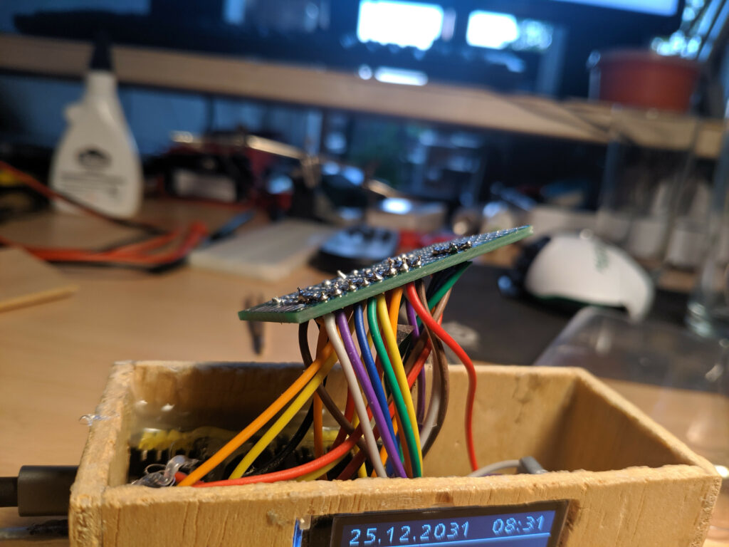
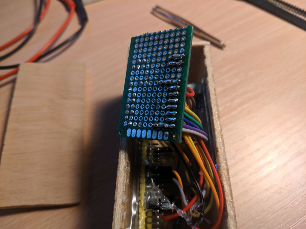
The left side is a failed try and not in use.
The external sensor and the usb power adapter are connect through sockets on the side cover:
Component architecture
20:05 by chris
In the following, you can find a UML component diagram of the software architecture:
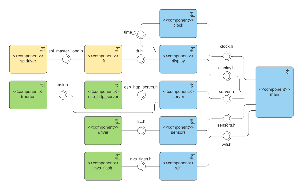
The blue colored components are developed by myself for this project. The yellows are integrated from the ESP32_TFT_library to control the display and the greens originate from the ESP-IDF.
Sensors Component
23:52 by chris
The sensors component controls the barometric sensors. It has the functions in it’s export interface:
- Init sensors at the start:
void init_sensors() - Start a measurement on the first sensor and write results to pointer parameters:
@param temp: pointer to the memory region for the resulting temp
@param press: pointer to the memory region for the resulting pressure
@param humid: pointer to the memory region for the resulting humidity
void read_sensor(int32_t* temp, uint32_t* press, uint32_t* humid); - Equivalent for the second sensor:
read_sensor2(...)
The component uses the provided Bosch library. It implements all device specific commands and measurement correction, but needs an interface for communication being implemented on the platform it runs on. The functions of the interface are:
I²C Delay
void user_delay_ms(uint32_t period)
{
    /*
     * Return control or wait,
     * for a period amount of milliseconds
     */
}
Implementation:
void i2c_delay(uint32_t period) {
vTaskDelay(period / portTICK_PERIOD_MS);
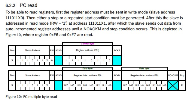
} I²C Read
int8_t user_i2c_read(uint8_t dev_id, uint8_t reg_addr, uint8_t *reg_data, uint16_t len)
{
    int8_t rslt = 0; /* Return 0 for Success, non-zero for failure */
    /*
     * The parameter dev_id can be used as a variable to store the I2C address of the device
     * Data on the bus should be like
     * |------------+---------------------|
     * | I2C action | Data                |
     * |------------+---------------------|
     * | Start      | -                   |
     * | Write      | (reg_addr)          |
     * | Stop       | -                   |
     * | Start      | -                   |
     * | Read       | (reg_data[0])       |
     * | Read       | (....)              |
     * | Read       | (reg_data[len - 1]) |
     * | Stop       | -                   |
     * |------------+---------------------|
     */
    return rslt;
}
Implementation:
int8_t i2c_read(uint8_t dev_id, uint8_t reg_addr, uint8_t *data, uint16_t len) {
i2c_cmd_handle_t cmd = i2c_cmd_link_create();
i2c_master_start(cmd);
i2c_master_write_byte(cmd, dev_id << 1 | I2C_MASTER_WRITE, 1);
i2c_master_write_byte(cmd, reg_addr, 1);
i2c_master_start(cmd);
i2c_master_write_byte(cmd, dev_id << 1 | I2C_MASTER_READ, 1);
if (len > 1) {
i2c_master_read(cmd, data, len - 1, I2C_MASTER_ACK);
}
i2c_master_read_byte(cmd, data + len - 1, I2C_MASTER_NACK);
i2c_master_stop(cmd);
i2c_master_cmd_begin(I2C_NUM_0, cmd, 500 / portTICK_RATE_MS);
i2c_cmd_link_delete(cmd);
return 0;
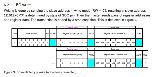
}I²C Write
int8_t user_i2c_write(uint8_t dev_id, uint8_t reg_addr, uint8_t *reg_data, uint16_t len)
{
    int8_t rslt = 0; /* Return 0 for Success, non-zero for failure */
    /*
     * The parameter dev_id can be used as a variable to store the I2C address of the device
     * Data on the bus should be like
     * |------------+---------------------|
     * | I2C action | Data                |
     * |------------+---------------------|
     * | Start      | -                   |
     * | Write      | (reg_addr)          |
     * | Write      | (reg_data[0])       |
     * | Write      | (....)              |
     * | Write      | (reg_data[len - 1]) |
     * | Stop       | -                   |
     * |------------+---------------------|
     */
    return rslt;
}
Implementation:
int8_t i2c_write(uint8_t dev_id, uint8_t reg_addr, uint8_t *data, uint16_t len) {
	i2c_cmd_handle_t cmd = i2c_cmd_link_create();
	i2c_master_start(cmd);
	i2c_master_write_byte(cmd, (dev_id << 1) | I2C_MASTER_WRITE, 1);
	i2c_master_write_byte(cmd, reg_addr, 1);
	i2c_master_write(cmd, data, len, 1);
	i2c_master_stop(cmd);
	i2c_master_cmd_begin(I2C_NUM_0, cmd, 500 / portTICK_RATE_MS);
	i2c_cmd_link_delete(cmd);
	return 0;
}
After implementing these interface functions, you can use the library functionality to read from the sensors.
The I²C driver from the ESP-IDF needs to be initialized first:
void i2c_setup()
{
	printf("Setting up I2C driver on port 1... ");
	i2c_config_t config;
	config.mode = I2C_MODE_MASTER;
	config.sda_io_num = 33;
	config.sda_pullup_en = GPIO_PULLUP_ENABLE;
	config.scl_io_num = 32;
	config.scl_pullup_en = GPIO_PULLUP_ENABLE;
	config.master.clk_speed = 100000;
	i2c_param_config(I2C_NUM_0, &config);
	printf("Set driver parameters... ");
	esp_err_t err = i2c_driver_install(I2C_NUM_0, I2C_MODE_MASTER, 0, 0, 0);
	if (err == ESP_OK)
		printf("Driver installed!\n");
	else if (err == ESP_ERR_INVALID_ARG)
		printf("Driver install failed, invalid arguments!\n");
	else
		printf("Driver install failed!\n");
}
Above is just ESP-IDF functions, the Bosch libs are not used until know.
Then you need to fill a config struct for a sensor:
dev = malloc(sizeof(struct bme280_dev));
dev->dev_id = 0x76;
dev->intf = BME280_I2C_INTF;
dev->read = i2c_read;
dev->write = i2c_write;
dev->delay_ms = i2c_delay;
bme280_init(dev);
And finally there can a measurement be started:
void read_sensor(int32_t* temp, uint32_t* pressure, uint32_t* humidity) {
	uint8_t settings_sel;
	uint32_t req_delay;
	struct bme280_data comp_data;
	dev->settings.osr_h = BME280_OVERSAMPLING_16X;
	dev->settings.osr_p = BME280_OVERSAMPLING_16X;
	dev->settings.osr_t = BME280_OVERSAMPLING_16X;
	dev->settings.filter = BME280_FILTER_COEFF_16;

	settings_sel = BME280_OSR_PRESS_SEL | BME280_OSR_TEMP_SEL | BME280_OSR_HUM_SEL | BME280_FILTER_SEL;
	bme280_set_sensor_settings(settings_sel, dev);

	req_delay = 12*bme280_cal_meas_delay(&(dev->settings));

	bme280_set_sensor_mode(BME280_FORCED_MODE, dev);
	dev->delay_ms(req_delay / portTICK_PERIOD_MS);
	bme280_get_sensor_data(BME280_ALL, &comp_data, dev);
	*temp = comp_data.temperature;
	*pressure = comp_data.pressure;
	*humidity = comp_data.humidity;
}
Here a measurement with maximum oversampling is started in forced mode (the sensor immediatly takes the measurement and goes back to sleep afterwards). The compensation data is calibration data in the sensor and is used to correct the readings. After the measurement is taken, the results are stored in the memory regions of the corresponding pointers.
Links
28.04.2020 00:32 by chris
| Source Code Repo | https://git.skalarprodukt.de/chris/Weather_ESP |
| ESP-IDF Docs | https://docs.espressif.com/projects/esp-idf/en/release-v4.0/api-reference/index.html |
| I²C Description (german) | https://www.rahner-edu.de/grundlagen/signale-richtig-verstehen/i2c-besser-verstehen-1/ |
| Bosch BME driver repo | https://github.com/BoschSensortec/BME280_driver |
Earthviewer
04.12.2015 21:52 by chris
Earthviewer is a small project, which renders a moving model of the Earth using a bunch of textures and some other cg tricks. Currently I am implementing atmospheric scattering.
Dieses Video sowie der folgende Download basieren auf Revision EEAA90CE.
Earthviewer Download
Visual C++ x86 Runtime Try to install this, if there is an error message while starting.
Appreciation
06.12.2015 17:46 by chris
When creating Earthviewer, I used a bunch of free libraries and assets. Here are the most important ones:
Libs
- Open Asset Import Library: 3D model import library
- Simple and Fast Multimedia Library: Multimedia framework, used for OpenGL context creation and window event handling
- AntTweakBar: Provides an easy way of creating a small GUI for tweaking variables. I used it as a debug tool for viewing variable values at runtime.
Assets
- Natural Earth III: Earth image data, going from texture maps to elevation maps. I used a night texture, a cloud map and the land/water mask.
- NASA Visible Earth – The Blue Marble: This is where the day texture is from and I also used one of their Bathymetry maps.
- Ponies & Light Normal Map: The personal blog of @tgfrerer, he wrote an article about extracting normal maps from elevation data. I used his results in my project.
- Milky Way Skybox Textures: Originally made for Kerbal Space Program using Space Engine. Unfortunately I do not know the author because of his reddit and mediafire account being deleted.
I also want to appreciate some tutorials which helped me alot:
Tutorials
- Wikibooks Arcball Camera
- Rastergrid – Efficient Gaussian blur with linear sampling
- Philip Rideout – OpenGL Bloom Tutorial
Exec Guildpage
24.03.2016 01:44 by chris
With the release of the World of Warcraft expansion “Warlords of Draenor”, I joined the German raiding guild “Exec”. At that time, they were using a GildenDKP website, which was quite costly and inflexible. So I made a new guild website. You can find an archived copy here!
Requirements
- Message board: The guild members should be able to communicate outside the game using a forum software, including all expected functions (thread-based conversation, private messaging, …).
- Voice communication: There should be some kind of voice communication service for talking while playing but also for out of game conversation. Since a World of Warcraft raid can consist of up to 30 individuals, the service had to support such group sizes.
- Homepage: The guild also needed a guild homepage for recruitment and news postings.
Aside from these functional requirements it was also necessary, that an interested novice would be able to handle basic administrative tasks.
Possible Extensions
- DKP-System: DKP are some kind of reward points, which each guild member earns and spends. An additional design target was to implement a system for DKP management.
- Simulationcraft: Simulationcraft is an open-source combat simulation tool, which is used by players to optimize their characters. Since it is a bit difficult to use for some people, we planned to provide all guild members with a daily simulation of their characters.
- Warcraftlogs: Warcraftlogs is a combat logging site, which analyses and visualizes uploaded combat logs. Since Warcraftlogs does not provide an API we just wanted to embed it into our page.
- Progression Banner: Many raiding guilds use a banner on their homepages to show their current raiding progress.
- Voice server monitor: It would have been convenient for the users to be able to view the current visitors on the voice server from the site.
Software Used
Implementation
Since a content management system would be required, this was an obvious place to start. First test installations with common CMS like Joomla, Drupal, e107 and WordPress were made. In the end Joomla has been chosen because of it’s great market share (which results in a larger quantity of available plugins) and great documentation. The administrative backend was quite convincing too. e107 and Drupal did have a lot less plugins and WordPress’ scope was more on blogging than content management.
The next step was the forum software. First some tests with the Joomla plugin Kunena have been made, but it got discarded. It’s default look wasn’t too great and the navigation wasn’t very intuitive. So I had to integrate some fully fledged bulletin board software with Joomla. Two different systems were reviewed (PhpBB and Simple Machines Forum) and since the PhpBB Homepage had been hacked and therefore wasn’t available for days, I chose SMF.
The licences of Joomla (GPLv2) and SMF (BSD) are incompatible, so there is no direct login bridge available in form of a SMF plugin. After some research I found JFusion, which is a more general approach to integrate software into Joomla. It is implemented as Joomla plugin and provides “adapters” to different platforms esp. SMF. At first I configured JFusion to authenticate users against the SMF database, so that SMF was the place to keep user data. Next JFusion provided a login module for Joomla that also sets SMF related auth cookies when logging in into Joomla, so users only need to use Joomla’s login form. To make it less confusing, I hid the login button in SMF. Lastly I used the frame wrapper of JFusion to embed SMF into Joomla as a menu entry (see demo).
In the next step I created a Joomla template from scratch and searched for a fitting SMF template, which I found in “Flat”. I adjusted both templates to integrate into each other.
Now let’s visit the extensions:
- Voice server monitor: This one was easy, because there are plenty Teamspeak viewer modules for Joomla.
- Progression Banner: For this design target, I wrote a small Joomla module, which used WoWProgress to pull progression data. Since they don’t provide an API, I used some regular expressions to parse their website. To reduce the performance impact of sending requests to another server, I used Joomla’s cache so that progression was only pulled once every hour.
- Warcraftlogs: I used Joomla’s iframe wrapper module for embedding Exec’s guild overview page on Warcraftlogs.
- DKP-System: To provide a first band aid solution I embedded a Microsoft Live spreadsheet into an iframe wrapper. I planned to implement a more convenient solution, like installing EQdkp in the background and embed some of it’s pages directly or writing a small home brew solution in form of an Joomla plugin. This did not become reality before I left.
- Simulationcraft: This never has been implemented, but since we had some simc-files already it would not have been too difficult to implement. Simc already produces HTML files while simulating, so it would have been possible to run it by a cronjob. It’s result HTML files would have been accessed by the webserver directly.
For voice communication I used Teamspeak, because the users were already used to it. Alternatives like Ventrilo or Mumble were not evaluated.
Demo
I have stopped playing World of Warcraft, so I am not with this guild anymore. That is why I took the original site offline, but I still want to use it for demonstration purposes. Using WinHTTrack I rendered all dynamic PHP-pages to static HTML pages. That way you can still view the site, but I don’t have to maintain it anymore. If you are interested, here is the link!
Review
In Retrospect Joomla wasn’t the best choice. It is a very complex system and esp. the SMF integration required a lot of tinkering before it worked. Even then, there were different small bugs, for example the WYSIWYG-editor in SMF did not catch some key events under some browsers when using the frameless wrapper. Another example is that the iframe wrapper is not able to adjust it’s size after loading, so when SMF changes it’s size (it has some pulldown menus), scroll bars were appearing. Adjusting two templates (one for Joomla and one for SMF) was really time consuming, even though I used an existing for SMF. I kept finding small errors on some sub pages in SMF quite a time after building the page.
Having to manage two systems (Joomla and SMF) didn’t help very much for making administrative tasks easy to handle. Our novice admins were confused quite badly.
JFusion’s login bridging worked quite well after some initial difficulties and Joomla’s plugin and template framework provided great benefit when developing the progression banner and the template.
So the most important caveat of Joomla was the lack of a good forum component. I might choose WordPress next time, because it seems to have a good forum plugin in form of bbPress (I didn’t test it very intensively though). It also provides all CMS functionality we needed and is more easy to manage because it doesn’t require admins to handle two separate systems.
Ray-Sphere Intersection
10.01.2018 19:02 by chris
When developing atmospheric scattering shaders, we will need to calculate intersection points between rays and spheres. So here is how we can do that.
Defining a ray
To define a ray, we specify two vectors: One point o, which goes from zero to a point on the ray and another one d, which goes along the ray and defines therefore the ray’s direction. The direction vector is multiplied by an argument t. When varying t, we can reach any point on the ray. Now you might say, that we did not define a ray, but a line. The only difference between rays and lines is, that t has a minimum value for rays. A line goes from -infinity to infinity, while a ray has a starting point and goes to infinity from there. In our use case, that’s not that important tough.

Defining a sphere
To define a sphere, we need to specify a center point c and a radius r. All points on a sphere are points, which have a distance to the center point equally to the sphere’s radius. So a sphere’s definition can be: 

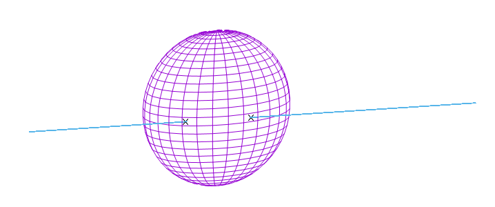
Intersecting both
In our use case, we will have the spheres always centered, so we can use the easier version of the sphere definition. Inserting the ray definition into the sphere definition yields:


Image a vector 

From the definition of the dot product and
So there is


To apply this to the intersection, we need to square it first:

\cdot(\overrightarrow{o}+t_{\mathrm{hit}}\overrightarrow{d})")
^2 =\overrightarrow{o}^2+2\overrightarrow{o}\cdot\overrightarrow{d}t_{\mathrm{hit}}+\overrightarrow{d}^2t_{\mathrm{hit}}^2")


To make the calculation easier we assume, that 

Now we use the reduced quadratic formula to solve the equation for
The discriminant is
So the cheapest way to calculate the intersection point is:

^2-q")

^2-\overrightarrow{o}^2+r^2}")
^2-\overrightarrow{o}^2+r^2}")


Keep in mind, that 